
Conditions for riser-free casting of ductile casting iron parts
The key to riser-free casting of ductile iron parts is to use the graphitization expansion effect during the solidification process to offset the shrinkage defects, but it is necessary to strictly control the materials, processes and design conditions. The following are the key conditions and detailed analysis for riser-free casting:
1. Materials and metallurgical conditions
1.1. Carbon equivalent (CE) optimization
Target range: CE = 4.3%~4.7% (C+Si/3), high carbon equivalent promotes full graphitization and significantly enhances the expansion pressure.
Key points for control:
Carbon content: 3.6%~3.9%, silicon content: 2.0%~2.5% (avoid excessively high content to cause graphite floating);
Residual magnesium (Mg residual): 0.03%~0.05%, rare earth (RE residual): 0.01%~0.03%, ensure that the spheroidization rate is ≥90%.
1.2. Low shrinkage tendency alloy design
Control sulfur (S < 0.015%) and phosphorus (P < 0.04%) to reduce shrinkage and inclusions.
2. Casting mold rigidity requirements
High strength of molding sand
Resin sand: Furan resin sand compressive strength ≥ 1.5 MPa, wet molding sand compaction rate ≥ 85% (B-type hardness tester);
Rigid support: Thick and large pieces use chromite sand or zircon sand for local reinforcement to resist cavity deformation caused by expansion pressure.
Sand box design
Use high-strength steel sand box, with iron or bolt locking to prevent lifting;
Sand box sand intake ≥ 80~100mm (more than 2 times the wall thickness of the casting) to ensure the constraint of the molding sand.
3. Process parameter control
Pouring temperature and speed
Temperature range: 1380~1420℃ (upper limit for thin-walled parts and lower limit for thick-walled parts). Too high will aggravate shrinkage, too low will cause poor fluidity;
Pouring time: fast and stable filling (pouring speed ≥1.5kg/s) to avoid oxidation of molten iron and temperature loss.
Cooling rate control
Chilling iron arrangement: set external chilling iron in the hot zone area (such as the wall thickness mutation point) to accelerate local solidification and form a sequential solidification gradient;
Insulation measures: cover the thick and large parts with insulation cotton or heating riser sleeve to delay solidification and use graphite expansion to compensate for shrinkage.
4. Casting structure design
Uniform wall thickness principle
Wall thickness difference ≤2:1 to avoid isolated hot zones; when it cannot be avoided, add process ribs or disperse the inner gate.
Minimum wall thickness ≥6mm (to prevent insufficient expansion due to excessive cooling).
Shrinkage channel design
The molten iron flow is guided through the inner gate or blind riser to form a solidification sequence from thin to thick;
“Self-shrinkage unit” (such as local boss) is set in the thick area to use its own expansion pressure to compensate for shrinkage.
5. Key verification and testing
Solidification simulation analysis
Use MAGMA or ProCAST software to simulate the solidification process to ensure that the expansion pressure is greater than the shrinkage amount (safety factor ≥ 1.2);
Focus on monitoring the shrinkage risk in the hot zone area (Niyama criterion > 1℃¹/²·min⁻¹/²).
Physical verification method
Anatomical detection: Cut typical castings and observe internal shrinkage defects (rated ≤ 2 according to ASTM E155);
Ultrasonic flaw detection (UT): Detect the density of thick wall areas (defect echo amplitude <Φ2mm flat bottom hole equivalent).
6. Typical application cases
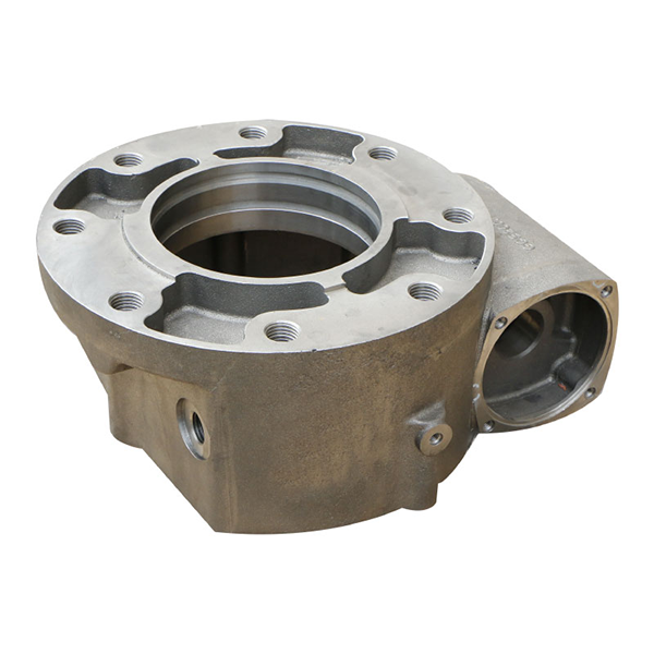
Case: QT500-7 reducer housing of a certain brand (wall thickness 10~40mm, weight 120kg).
Process plan:
CE=4.5% (C=3.7%, Si=2.4%), Mg residue=0.04%;
Resin sand molding, sand box sand intake 100mm, iron lock;
Pouring temperature 1400℃, chiller arranged at the root of 40mm thick flange;
Solidification simulation shows that expansion pressure covers shrinkage demand, and the actual casting UT test pass rate is>98%.
7. Common problems and countermeasures
Problem phenomenon Cause analysis Solution
Local shrinkage (hot spot area) Insufficient expansion pressure or low sand rigidity Increase chiller, optimize CE value, and improve sand mold strength
Surface depression Shrinkage compensation interruption at the end of solidification Adjust the pouring system and extend the holding time
Graphite floating Carbon equivalent is too high or pouring temperature is too high Reduce CE to below 4.5%, control pouring temperature <1420℃
Summary
To achieve riser-free casting of ductile iron, it is necessary to systematically control the three core elements of high carbon equivalent metallurgical design, high rigidity casting, and directional solidification process. By combining simulation optimization with physical verification, costs can be significantly reduced and production efficiency can be improved. However, parameters need to be dynamically adjusted according to the specific casting structure to ensure the adequacy and reliability of expansion and shrinkage compensation.