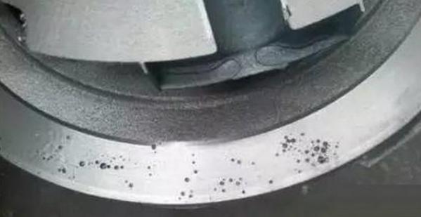
1: Porosity (bubbles, choking holes, air pockets)
Features: Porosity is a hole on the surface or inside of a casting, which is round, oval or irregular in shape. Sometimes multiple pores form an air mass, and the subcutaneous is generally pear-shaped. Choking holes are irregular in shape and have a rough surface. Air pockets are a concave area on the surface of the casting, and the surface is relatively smooth. The appearance inspection of the open hole can be found, and the subcutaneous pores can only be found after mechanical processing.
Causes:
- The mold preheating temperature is too low, and the liquid metal cools too quickly when passing through the pouring system.
- The mold exhaust design is poor, and the gas cannot be discharged smoothly.
- The coating is not good, the exhaust performance itself is poor, and it even volatilizes or decomposes gas.
- There are holes and pits on the surface of the mold cavity. After the liquid metal is injected, the gas in the holes and pits expands rapidly and compresses the liquid metal, forming choking holes.
- The surface of the mold cavity is rusted and not cleaned.
- The raw materials (sand cores) are improperly stored and not preheated before use.
- Poor deoxidizer, insufficient dosage or improper operation, etc.
Prevention methods: - The mold should be fully preheated, the particle size of the coating (graphite) should not be too fine, and the air permeability should be good.
- Use tilted pouring method for pouring.
- The raw materials should be stored in a ventilated and dry place, and preheated when used.
- The pouring temperature should not be too high.
2: Shrinkage (shrinkage)
- Features: Shrinkage is a rough surface hole on the surface or inside of the casting. Slight shrinkage is many scattered small shrinkage holes, that is, shrinkage, shrinkage or shrinkage. The grains are coarse. It often occurs near the pouring channel in the casting, the root of the riser, the thick part, the thick and thin transition of the wall, and the thick and thin parts with large planes.
- Causes:
- The working temperature control of the mold does not meet the requirements of directional solidification.
- Improper coating selection, and the thickness of the coating layer in different parts is not well controlled.
- The position of the casting in the mold is improperly designed.
- The design of the pouring and riser fails to fully compensate for shrinkage.
- The pouring temperature is too low or too high.
Prevention and control methods: - Increase the mold temperature.
- Adjust the thickness of the coating layer, spray the coating evenly, and do not form local coating accumulation when the coating falls off and is reapplied.
- Locally heat the mold or use insulation materials to locally insulate.
- Insert copper blocks in the hot spots to chill the local areas.
- Design heat sinks on the mold, or accelerate the cooling speed of local areas through water, or spray water or spray outside the mold.
- Use detachable chilling blocks and place them in the cavity in turn to avoid insufficient cooling of the chilling blocks themselves during continuous production.
- Design a pressurizing device on the mold riser.
- The pouring system design should be accurate and the appropriate pouring temperature should be selected.
3: Slag holes (flux inclusions or metal oxide inclusions)
Features: Slag holes are open or dark holes on castings. The holes are filled with slag in whole or in part. The shape is irregular. Small dots of flux inclusions are not easy to find. After the slag is removed, smooth holes are presented. They are generally distributed in the lower part of the pouring position, near the inner runner or in the dead corner of the casting. Oxide inclusions are mostly distributed in a mesh on the surface of the casting near the inner runner. Sometimes they are in the form of thin sheets, or irregular clouds with wrinkles, or form a sheet-like interlayer, or exist in the form of flocs inside the casting. When broken, they often break from the interlayer. The oxide is in it, which is one of the sources of cracks in the casting.
Causes of formation: Slag holes are mainly caused by the alloy smelting process and pouring process (including incorrect design of the pouring system). The mold itself will not cause slag holes, and metal molds are one of the effective ways to avoid slag holes.
Prevention and control methods:
- The pouring system is set correctly or a casting fiber filter is used.
- Use an inclined pouring method.
- Select flux and strictly control quality.
4: Cracks (hot cracks, cold cracks)
Features: The appearance of cracks is straight or irregular curves. The surface of the hot crack fracture is strongly oxidized and dark gray or black, without metallic luster. The surface of the cold crack fracture is clean and has metallic luster. Generally, the external cracks of the casting can be seen directly, while the internal cracks can only be seen with the help of other methods. Cracks are often associated with defects such as shrinkage and slag inclusions. They often occur on the inside of the sharp corners of the casting, at the junction of thick and thin sections, and in the hot zone where the pouring head and the casting are connected.
Causes: Metal mold casting is prone to crack defects, because the metal mold itself has no yielding properties and cools quickly, which can easily cause the internal stress of the casting to increase. Opening the mold too early or too late, pouring angles that are too small or too large, and coating layers that are too thin can easily cause casting cracks. Cracks are also easy to cause when the mold cavity itself has cracks.
Prevention and control methods:
- Attention should be paid to the processability of the casting structure, so that the uneven wall thickness of the casting is evenly transitioned, and the appropriate fillet size is adopted.
- Adjust the coating thickness to make the various parts of the casting reach the required cooling rate as much as possible to avoid the formation of too much internal stress.
- Attention should be paid to the working temperature of the metal mold, adjust the mold slope, and timely core cracking, remove the casting and cool it slowly.
5: Cold shut (poor fusion)
Features: Cold shut is a through seam or surface seam with rounded edges, separated by oxide scale in the middle, not completely integrated, and becomes “undercast” when the cold shut is serious. Cold shut often appears on the top wall of the casting, thin horizontal or vertical surface, thick and thin wall joints or on thin auxiliary plates.
Causes:
- Unreasonable metal mold exhaust design.
- The working temperature is too low.
- Poor coating quality (artificial, material).
- The location of the runner is improper.
- The pouring speed is too slow, etc.
Prevention and control methods: - Correctly design the runner and exhaust system.
- For large-area thin-walled castings, the coating should not be too thin. Appropriately thickening the coating layer is conducive to molding.
- Appropriately increase the working temperature of the mold.
- Use the tilted pouring method.
- Use mechanical vibration metal mold pouring.
6: Sand holes (sand holes)
Features: Relatively regular holes are formed on the surface or inside of the casting, and its shape is consistent with the shape of the sand grains. When it is just out of the mold, the sand grains embedded on the surface of the casting can be seen, and the sand grains can be taken out from it. When multiple sand holes exist at the same time, the surface of the casting is orange peel-like.
Cause of formation: The sand grains falling from the surface of the sand core are wrapped by the copper liquid and exist on the surface of the casting to form holes.
- The surface strength of the sand core is not good, it is burnt or not completely solidified.
- The size of the sand core does not match the outer mold, and the sand core is crushed when the mold is closed.
- The mold is dipped in graphite contaminated with sand.
- The sand that falls off the sand core at the ladle and the runner is washed into the mold cavity with the copper water.
Prevention and control methods: - Strictly follow the production process when making the sand core and check the quality.
- The size of the sand core matches the outer mold.
- The ink should be cleaned in time.
- Avoid friction between the ladle and the sand core.
- Blow clean the sand in the mold cavity when placing the sand core